Design of Experiments in Freemelt ONE
Problem ‐ Slow Experiment Design
Freemelt ONE is an electron beam powder bed fusion (E-PBF) system tailored for materials research and development. It offers exceptional customizability by granting users unparalleled control over the entire build process. However, the abundance of possibilities can make it challenging to establish an organized development workflow. While flexibility is powerful, effective organization is essential to maximize its benefits.
Solution ‐ Organizing Experiments with Pixelmelt®
To expedite experiments and speed up development, Freemelt has introduced Pixelmelt®, a purpose‐built cloud‐based service, designed to address this challenge. Pixelmelt® offers the ideal solution for executing an evolutionary development strategy.
Experiment design using Pixelmelt® follows these stages:
- Create a CAD file of the desired build geometry and slice it into a .3mf file using compatible software.
- Import the .3mf file into Pixelmelt®, which will automatically divide the build area into pixels arranged in a square grid.
- Apply various melting algorithms, including ordered patterns, such as Snake and Single Directional, and randomized patterns, such as Stochastic and Probabilistic.
- Pixelmelt® will generate a complete build file with the chosen configurations.
- Build the objects and evaluate the results.
Pixelmelt® allows convenient partitioning of build objects between layers, enabling researchers to experiment with different settings and melting patterns. The cloud‐based architecture facilitates seamless sharing of experiments within an organization, thereby improving collaboration and workflow efficiency. Moreover, the user‐friendly and convenient configuration in Pixelmelt® makes it effortless to start batch experiments with Freemelt ONE.
Case ‐ Lattices
Freemelt developed lattice structures in titanium. The process involved:
Step one: Create a CAD file
Various lattice CAD files were designed and exported as .3mf files.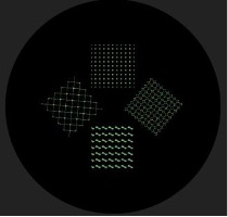 Figure 1: Different lattice patterns in Pixelmelt®.
Step two: Import the CAD file into Pixelmelt®
The .3mf file was imported into Pixelmelt® for partitioning and configuration.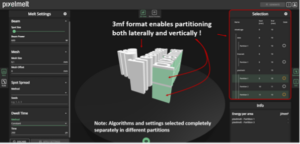 Figure 2: Pixelmelt®
Step three: Iterative experiments
Pixelmelt®’s strength shines in defining optimal melting settings. Determine the energy density range by:
- Build test objects, for example by varying the dwell time, with increasing energy density until material melting occurs.
- Build additional test objects to identify the upper energy density threshold to prevent overmelting and material swelling.
By building an object batch with a range of energy densities between the minimum and the maximum and choosing the best objects, the process can be further repeated to narrow the parameter space. This kind of evolutionary development is where Pixelmelt® excels.
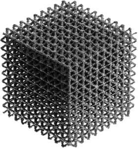 Figure 3: Lattice built in Freemelt ONE using Pixelmelt®
Advantages for Researchers
Incorporating Pixelmelt® into the experimentation process offers several advantages for researchers:
- Time and Cost Efficiency: The organized experiment design process and automation offered by Pixelmelt® significantly reduce the time and cost required for preparing builds.
- Batch Specialization: Pixelmelt® is tailored towards batch experiments, allowing researchers to easily experiment with different settings and melting patterns.
- Collaboration and Knowledge Sharing: The cloud‐based platform fosters collaboration among researchers, allowing them to quickly replicate builds and continue building upon previous work.
- Ease of Initiation: Quick build file creation with Pixelmelt®, eliminating coding requirements.
Conclusion
Pixelmelt® provides researchers with a practical solution for streamlining experiment planning and execution in E-PBF. It simplifies workflows, enhances cost‐effectiveness, facilitates collaboration, and synergizes effectively with Freemelt ONE.
Learn more about Freemelt ONE.
Learn more about Pixelmelt®.
2023-10-19 14:38:18